
Showing posts with label 3Ds max. Show all posts
Showing posts with label 3Ds max. Show all posts
Saturday, May 07, 2011
Combining 3D object with real photograph V2
With some comment from my sister, i re-edit my last piece to make it more realistic.. hope it does.. how do you think?


Wednesday, May 04, 2011
Combining 3D object with real photograph
Hi.. Its almost 5 month since my last post, showing how lazy I am to update this blog. I'm now focusing on 2D animation, but I never abandon 3D. Most of the time I use 3D to create object that is hard to draw, and then I render it using ink n paint.
But now I try to test something new to me. I'm trying to combine 3D object with real photograph. Its a tough job, and for this project I use my last 3D model, the old proton saga. Once I learn the trick, I try to apply on other render as well, and hopefully post it here.
Below is my test, I took a picture infront of my house, as the Background plate.
Then I render the model using mental ray matte/shadow/reflection shader.

But now I try to test something new to me. I'm trying to combine 3D object with real photograph. Its a tough job, and for this project I use my last 3D model, the old proton saga. Once I learn the trick, I try to apply on other render as well, and hopefully post it here.
Below is my test, I took a picture infront of my house, as the Background plate.
Then I render the model using mental ray matte/shadow/reflection shader.

Sunday, September 26, 2010
Setting that I use for Ambient occlusion and Ink n paint
Hi,
Even though no one ask me for this, I hope i can help someone who want to achieve the same ink n paint + AO render as mine.
Below is the setting I use for the AO (click to enlarge) :

Below is the setting I use for 'Ink n Paint' material :

Tips for mental ray users : If you want to assign all object to the same material, use 'material override' in Mental ray render setup -> Processing -> material override and drag to the button.

Hope that helps! thanks for your visit
Even though no one ask me for this, I hope i can help someone who want to achieve the same ink n paint + AO render as mine.
Below is the setting I use for the AO (click to enlarge) :

Below is the setting I use for 'Ink n Paint' material :

Tips for mental ray users : If you want to assign all object to the same material, use 'material override' in Mental ray render setup -> Processing -> material override and drag to the button.

Hope that helps! thanks for your visit
Tuesday, September 21, 2010
Failed Project explained...
Hi,
Regarding my last project, the proton Exora MPV, there is a problem which lead to the halt of the project. It is about all its glass windows, including the front windshield.

From the picture above, you can see that the window is not smooth. It looks like a piece of soft plastic or wrapping paper..
After trying to fix the problem several times, it seems that the problem lies in my modeling technique, where I modeled the chassis and window seperately, as pictured above.
The problem requires a major modification on the polygons, thus I decided to put this model onto halt.
I however managed to prove my theory on my next 3D models. Below is the new model :
 I model the chassis together with the windows and windshield. The polygons of the windows were only detached after the modeling of the required parts is complete. For example, I modeled the door altogether with the windows in 1 piece. Once I complete the door, I then select the polygon which makes the windows, then press the 'detach' button, to seperate the window from the door.
Although I didnt manage to complete the model, I've learn a valuable lesson. Hopefully I'll be able to do better models soon.
Regarding my last project, the proton Exora MPV, there is a problem which lead to the halt of the project. It is about all its glass windows, including the front windshield.

From the picture above, you can see that the window is not smooth. It looks like a piece of soft plastic or wrapping paper..

The problem requires a major modification on the polygons, thus I decided to put this model onto halt.
I however managed to prove my theory on my next 3D models. Below is the new model :

Although I didnt manage to complete the model, I've learn a valuable lesson. Hopefully I'll be able to do better models soon.
Sunday, July 11, 2010
UVW map modifier.
Okay, as promised, here is the UVW map tutorial. This is a very basic technique to texturing, and its a prelude to my next tutorial, Unwrap UVW mapping.
UVW is a coordinate system for textures. it is almost similar to XYZ system, with U represent X axis of the 2D surface (your 3D model surface), V represent Y axis. You might ask why 2D plane have a Z axis (depth)? This is for the system to recognize normal or flipped texture. It is used mostly on procedural map and it does not effect your normal bitmap texture.
So why you need to apply the UVW map modifier. If you are applying your texture to your 3D model by simply dragging it to the model and hoping it will come right, you might face problem later when one time you have complex model to texture. Model that is build using line and extrude modifier will also face this problem most of the time.
If you use the coordinate rollout inside the diffuse bitmap material box, he Tiling and Offset thingy to coordinate your texture on the model, you also might face problem later if you want to use the same material on other polygons.
So, here the UVW map come to the rescue.
UVW map allow you to set the coordinate/position of your model texture individually. Let say you have a 3D house model. You want to use brick texture. At first on the front of the house you may want to have a different look, by tilting the brick at 70 degree, with the size of brick that is suitable for it. However, at the other parts such as the pillar, you want the brick to have bigger brick size and aligned horizontally. This is possible by using UVW map modifier separately for each object (wall and pillar).
Below is the basic method on how to use UVW map on a simple box.
First, create a simple box.

Open material browser, click the diffuse map, the pop-up list, choose bitmap.
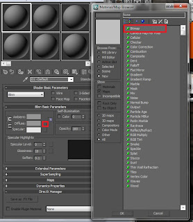
Choose any texture that you like, in this tutorial I use a brick texture.

Click the show standard map in viewport. Drag the brick slot onto the material.

Select the box, and on the modify panel, modifier, choose UVW map
 There are several options on the parameter rollout after you apply the UVW mapping to the box.

For this lessons, we choose Box mapping, and on the Alignment sub-section below, choose Fit. It will automaticly adjust the map gizmo to fit the selected object. You can try to experiment the Alignment XYZ radio button and see the results.

To adjust, use the U/V tile shown in picture below. adjust to your liking.

click the UVW Mapping modifier on the modifier stack. The word Gizmo will be shown. click the gizmo word.

You can adjust the gizmo box by using move and rotate tool.

Thats all for the tutorial. On the next tutorial I will share with you on how to use UVW unwrap.
UVW is a coordinate system for textures. it is almost similar to XYZ system, with U represent X axis of the 2D surface (your 3D model surface), V represent Y axis. You might ask why 2D plane have a Z axis (depth)? This is for the system to recognize normal or flipped texture. It is used mostly on procedural map and it does not effect your normal bitmap texture.
So why you need to apply the UVW map modifier. If you are applying your texture to your 3D model by simply dragging it to the model and hoping it will come right, you might face problem later when one time you have complex model to texture. Model that is build using line and extrude modifier will also face this problem most of the time.
If you use the coordinate rollout inside the diffuse bitmap material box, he Tiling and Offset thingy to coordinate your texture on the model, you also might face problem later if you want to use the same material on other polygons.
So, here the UVW map come to the rescue.
UVW map allow you to set the coordinate/position of your model texture individually. Let say you have a 3D house model. You want to use brick texture. At first on the front of the house you may want to have a different look, by tilting the brick at 70 degree, with the size of brick that is suitable for it. However, at the other parts such as the pillar, you want the brick to have bigger brick size and aligned horizontally. This is possible by using UVW map modifier separately for each object (wall and pillar).
Below is the basic method on how to use UVW map on a simple box.
First, create a simple box.

Open material browser, click the diffuse map, the pop-up list, choose bitmap.

Choose any texture that you like, in this tutorial I use a brick texture.

Click the show standard map in viewport. Drag the brick slot onto the material.

Select the box, and on the modify panel, modifier, choose UVW map


For this lessons, we choose Box mapping, and on the Alignment sub-section below, choose Fit. It will automaticly adjust the map gizmo to fit the selected object. You can try to experiment the Alignment XYZ radio button and see the results.

To adjust, use the U/V tile shown in picture below. adjust to your liking.

click the UVW Mapping modifier on the modifier stack. The word Gizmo will be shown. click the gizmo word.

You can adjust the gizmo box by using move and rotate tool.

Thats all for the tutorial. On the next tutorial I will share with you on how to use UVW unwrap.
Saturday, November 07, 2009
Distributed Rendering using mental Ray

3D rendering using combined 1 quadcore computer and 1 dualcore computer.
Quadcore : AMD Athlon II X4 620 2.6Ghz @ 2.9Ghz OC - 2GB RAM
Dualcore : Intel Core 2 Duo E8300 2.83Ghz - 1GB RAM
3D Software : 3Ds Max 2010
Renderer : Mental Ray 3.7
Thursday, November 05, 2009
Tutorial - How to create realistic Lighting in 3Ds Max
Someone has asked me how I do the lighting setup for my 3D car render, so here it is.
(Click the picture to see full size)
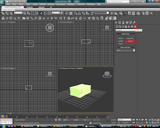
1) On the create panel, choose system. Then click Daylight to create a daylight system.
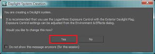
2) A dialog box will appear. Choose Yes
3) On Top viewport, click at anyplace to create the daylight system. I recommend you put the daylight system far from the object you created so that the icon doesnt mess up wih your object. The method of creation is : First you create a compass. Then another click you will be setting the height of the sun system. You dont have to worry about the exact height because Max will take care of this later when we set the parameter.
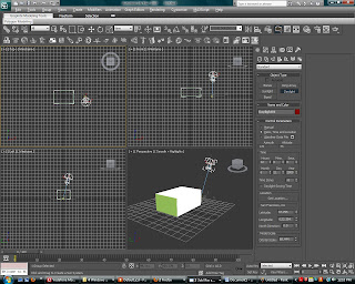
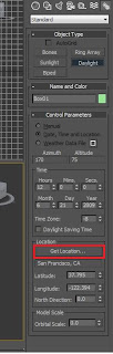
4) On the control parameter rollout on the right of your screen, click 'Get Location'
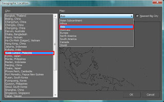
5) Choose geographic location for your scene setup. I choose Asia - Kuala Lumpur, Malaysia. Click OK.
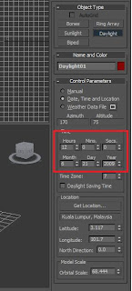
6) Then on the same rollout, set the time you desired.
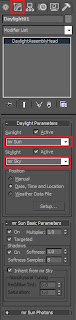
 7)Go to modify panel and on the Daylight Parameter rollout change the Sunlight system to 'mr Sun' and Skylight system to 'mr Sky'.
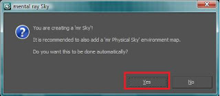
8) A dialog box will pop-up when you choose mr Sky. Choose Yes.
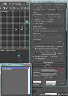
9) You need to set the renderer to Mental Ray for this thing to work. On Render setup, on the 'Assign Renderer' rollout, for production choose mental ray renderer.
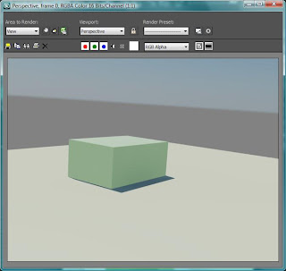
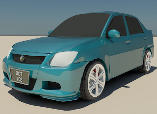
Both of the render below is the result of the lighting setup above.
Thank you. Comments in English and Malay are welcome
(Click the picture to see full size)
1) On the create panel, choose system. Then click Daylight to create a daylight system.

2) A dialog box will appear. Choose Yes

3) On Top viewport, click at anyplace to create the daylight system. I recommend you put the daylight system far from the object you created so that the icon doesnt mess up wih your object. The method of creation is : First you create a compass. Then another click you will be setting the height of the sun system. You dont have to worry about the exact height because Max will take care of this later when we set the parameter.

4) On the control parameter rollout on the right of your screen, click 'Get Location'

5) Choose geographic location for your scene setup. I choose Asia - Kuala Lumpur, Malaysia. Click OK.

6) Then on the same rollout, set the time you desired.
 7)Go to modify panel and on the Daylight Parameter rollout change the Sunlight system to 'mr Sun' and Skylight system to 'mr Sky'.
8) A dialog box will pop-up when you choose mr Sky. Choose Yes.

9) You need to set the renderer to Mental Ray for this thing to work. On Render setup, on the 'Assign Renderer' rollout, for production choose mental ray renderer.

Both of the render below is the result of the lighting setup above.

Thank you. Comments in English and Malay are welcome
Subscribe to:
Posts (Atom)